Overview
Following an attempted (and moderately successful, but never fired) case bond in spring 2021, I wanted to try again with a new and less janky system. The main problem I encountered before was insulator coverage on the ID of the motor casing—it had to be manually spread out with a dowel which led to lost insulator and uneven coverage. To combat that, I chose to overshoot the thickness to allow for proper coating. This time, the insulator weight summed to 1976 grams for 43.5” length and around .23” wall thickness (in a 4”x48” casing with .125” wall). The insulator formula is as follows:
Following an attempted (and moderately successful, but never fired) case bond in spring 2021, I wanted to try again with a new and less janky system. The main problem I encountered before was insulator coverage on the ID of the motor casing—it had to be manually spread out with a dowel which led to lost insulator and uneven coverage. To combat that, I chose to overshoot the thickness to allow for proper coating. This time, the insulator weight summed to 1976 grams for 43.5” length and around .23” wall thickness (in a 4”x48” casing with .125” wall). The insulator formula is as follows:
Spin Casting
In the past, I have spun cast the insulator and cast the propellant on the same day. This time, however, with the complex aft inhibitor geometry, the insulation needed to be fully cured before any further steps. I decided to cure at an index of 0.85 with a significant portion of cross-linker to open up bonding sites for the inhibitor and propellant cast later. It did great, and all interfaces were seamless.
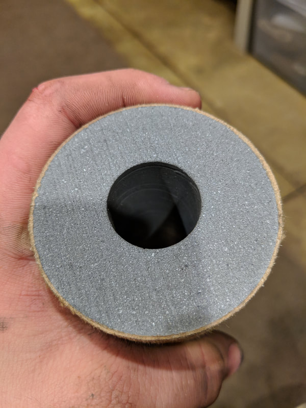
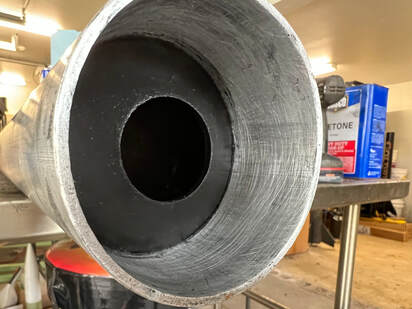
To spin cast, I mixed up the insulator and machined end plugs for the casing to space out the insulator from the ends. After mixing, I put one plug in and poured the insulator down the casing. I poured it all in, and rotated the casing to evenly space it out before spin casting. This did result in a taper of insulator thickness, with the thickest part being at the forward end, so I will need to pour from both ends in the future. After that, it was set on the spin caster and ran for around 20 hours. It spun at around 320 rpm. Picture of the completed spin cast:
In the past, I have spun cast the insulator and cast the propellant on the same day. This time, however, with the complex aft inhibitor geometry, the insulation needed to be fully cured before any further steps. I decided to cure at an index of 0.85 with a significant portion of cross-linker to open up bonding sites for the inhibitor and propellant cast later. It did great, and all interfaces were seamless.
To spin cast, I mixed up the insulator and machined end plugs for the casing to space out the insulator from the ends. After mixing, I put one plug in and poured the insulator down the casing. I poured it all in, and rotated the casing to evenly space it out before spin casting. This did result in a taper of insulator thickness, with the thickest part being at the forward end, so I will need to pour from both ends in the future. After that, it was set on the spin caster and ran for around 20 hours. It spun at around 320 rpm. Picture of the completed spin cast:
By this point, it was tacked up enough to not flow under gravity. So, I got to work on the inhibitor.
Inhibitor Casting
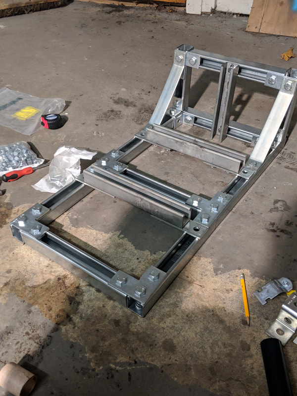
The geometry can be viewed here, with the left picture being the full CAD and the right picture the CAD of the casting assembly (3D printed parts in green):
Inhibitor Casting
The geometry can be viewed here, with the left picture being the full CAD and the right picture the CAD of the casting assembly (3D printed parts in green):
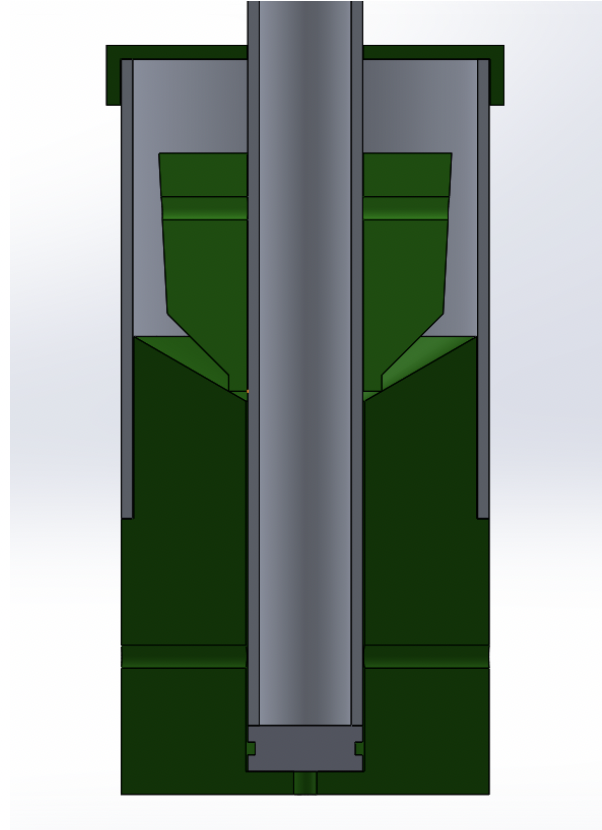
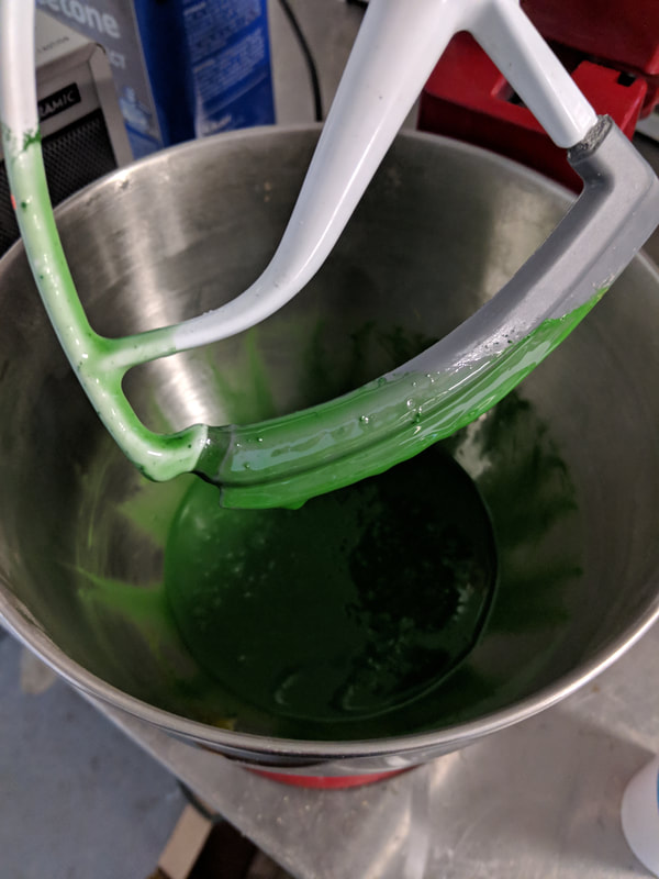
I poured the inhibitor, which was largely the same formula as the insulator save for some extra kevlar, into a syringe and injected it into the bottom of the casing with a dowel. After some vibration to remove voids, I inserted the positive (green) mold and let it cure. After curing (about a day), I took off the printed parts and cleaned all rubber surfaces to remove residue mold release:
Propellant
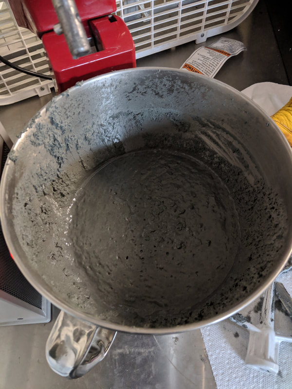
Finally, it was time for propellant. I inserted the casting plug (same as the inhibitor plug) and mandrel. I poured the propellant around the mandrel. Nothing to report here, it was a nominal casting. I then topped off the motor with forward inhibitor (not pictured). The forward inhibitor was just HTPB loaded with carbon black.
Finally, it was time for propellant. I inserted the casting plug (same as the inhibitor plug) and mandrel. I poured the propellant around the mandrel. Nothing to report here, it was a nominal casting. I then topped off the motor with forward inhibitor (not pictured). The forward inhibitor was just HTPB loaded with carbon black.
I then removed the mandrel the next day and glued the closures on with undercured HTPB mix loaded with carbon black. It is important to note that all casted rubber was undercured to promote bonding between different casting sessions. I need to do a proper peel test, but no seams were visible upon motor dissection. Finally, I pinned the closures in and the motor was ready for firing.
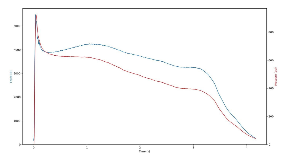
Due to a miscalculation in nozzle size, the motor ran steady state at around 400 psi. This was good for a preliminary test, as it will be easier on the insulator erosion, but a high pressure test still needs to happen (hopefully next run). The motor also had a full phenolic nozzle which eroded, leading to the regressive thrust profile:
Due to a miscalculation in nozzle size, the motor ran steady state at around 400 psi. This was good for a preliminary test, as it will be easier on the insulator erosion, but a high pressure test still needs to happen (hopefully next run). The motor also had a full phenolic nozzle which eroded, leading to the regressive thrust profile:
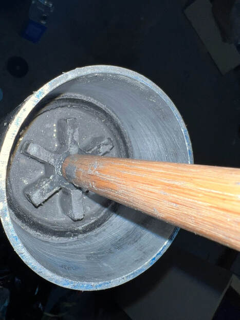
Upon dissection, almost no insulator was eroded. Even at the forward end where wall-burning occurred due to the finocyl fins, the insulator still retained most of its mass, plus a small char layer. Here are some cross section view pictures:
Some voids are visible in the inhibitor. While not a problem for this test, future tests could suffer. Vacuum and vibration will be needed to remove these.
Overall, the test was extremely successful. It vetted the inhibitor design, insulator composition, and the new upper-finocyl propellant geometry. On to the next high pressure test!
Overall, the test was extremely successful. It vetted the inhibitor design, insulator composition, and the new upper-finocyl propellant geometry. On to the next high pressure test!